
With the machine compensated for LRO begin the machining process with the scratch cut.
Your goal with the scratch is to reference the thinnest part of the rotor, as you will add your cut depth to this point. Generally you will be removing at least .004" per side, or .008" total from the rotor beyond your scratch depth. If there are gouges in the rotor, use the deepest gouge as the reference point. All Pro-Cut lathes use a positive rake cutting tip that works best when used at a cutting depth of no less than .0025" and no more than .020" per side.
With the cutting head centered over the rotor and the tool arms separated enough to clear the rotor, wind the cutting head in to about 1/4" over the outer edge of the rotor surface and make a light scratch cut on both sides. Your scratch should be light, but deep enough to contact the rotor 360°. If there is significant rust or ridges, then go in far enough to land on a decent surface. Start your scratch on the inner side of the rotor first, and then on the outer side as you can hear the rear scratch but can't see easily. If there is a ridge to be removed on the outside edge, lock the tool arm lock lever(s) and engage the clutch to let the machine take off the ridge.
If you determined that the rotor is nearly evenly thick from outside to inside ( from your previous measurements), Back off the tool arms a set # of lines until the tips are no longer touching the rotor, then wind the clutch counterclockwise until the tips are advanced to within an 1/8" from the inside starting point of where your cut will begin.
Repeat the scratch from the back side first, then front by dialing the depth knobs the same # of lines you backed off in the previous step. Slowly wind the clutch counterclockwise until the tips are advanced to the starting point (inside most point of friction mating surface). Do not hit the hat of the rotor! Contact between the cutting tips and anything other than the rotor could damage the lathe or the rotor.
Now set your cut depth. If you've followed the measuring & scratch cut reference procedure properly, you should only need to cut at a depth of .004" to .0075" per side beyond the thinnest part of the rotor to accomplish a superior finish in one pass.
Remember, the depth of cut you select is determined by several factors including:
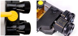
On the Speed Lock cutting head, each line on the knob represents .0025". There is a stationary reference line for you to use when setting the cut depth. On the 12XX series cutting head, each line on the knob represents .001".
Once your depth of cut is dialed in, lock the tool arm lock knob(s) and shut off the machine using either the micro-switch by the cutting head, or the main on/off switch on the electrical box. This is your last chance to double check set up before starting the cut. One last time, with the machine off do the following:
Note: Pro-Cut cutting tips should be the only cutting tips used in the lathe. They cannot be flipped upside down, but can be switched side to side. Dots must always face up.